
A few weeks ago, probably due to my recent Arduino and D-CPU obsessions, I started thinking about with this topic: How do modern computer CPUs add numbers? I took classes on this in school, so I had a basic understanding, but the more I thought about it, the more I realized that my ideas about how this would scale up to 64-bit computers would be too slow to actually work.
I started digging around, and even though wikipedia is usually exhaustive (and often inscrutable) about obscure topics, I had reached the edge of the internet. Only context-less names like “Kogge-Stone” and unexplained box diagrams greeted me. I had to do actual research of the 20th-century kind.
So come with me over the precipice and learn – in great detail – how to add numbers!
I’m going to start out as if you’ve never taken a class in computer engineering. If you’re familiar with the basics of binary addition, skip below to get to the good stuff.
Adding in binary
For big numbers, addition by hand means starting on the rightmost digit, adding all the digits in the column, and then writing down the units digit and carrying the tens over. In the example below, 8 plus 4 is 12, so we carry the 1, which I’ve indicated with a precious tiny blue 1 over the left column:
482
+345
----
827
We memorize this in school, but the reason it works is that each column is the same power of ten: 8 tens plus 4 tens is 12 tens. And 12 tens is really 1 hundred and 2 tens, so the 1 hundred is shifted/carried over to the hundreds column.
This works the same in binary, but the digits can only ever be 0 or 1, so the biggest number we can add is 1 plus 1. This would be 2, or “10” in binary (1 two and 0 ones), so there’s a carry of 1. In fact, if we have a carry, 1 plus 1 with a carried 1 is 3: “11” (1 two and 1 one). That still only carries a 1, which is convenient, because it means the carry can be represented in binary just like every other digit.
0110 (6)
+0111 (7)
-----
1101 (13)
So, to add two binary numbers, we just need to add 3 binary digits (one digit from each of the numbers, plus a possible incoming carry), and produce a sum bit and an outgoing carry bit. We can make a logic table for this:
| A | B | C | Carry | Sum |
|---|---|---|---|---|
| 0 | 0 | 0 | 0 | 0 |
| 0 | 0 | 1 | 0 | 1 |
| 0 | 1 | 0 | 0 | 1 |
| 0 | 1 | 1 | 1 | 0 |
| 1 | 0 | 0 | 0 | 1 |
| 1 | 0 | 1 | 1 | 0 |
| 1 | 1 | 0 | 1 | 0 |
| 1 | 1 | 1 | 1 | 1 |
…and then design a logic circuit to generate the Sum and Carry bits. In
logic circuit equations,
“+” means OR,
“⋅” means AND,
and “⊕” means XOR.
(Programmers usually use “&” to mean AND, and “|” to mean OR, but I
think in this case it’s important to use the symbols that professional circuit
designers use. It gives you a bit more intuition when dealing with logical
equations, which will come up later.)
One way to think of it is: According to the logic table we just made, the sum
should be 1 if there are an odd number of incoming 1s. XOR is the operation
that matches odd inputs. And the carry should be 1 if at least two of the
incoming digits are 1.
Adding in circuitry
The most straightforward logic circuit for this is
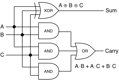
assuming you have a 3-input XOR gate. If you don’t, you can just hook two
2-input XOR gates together.
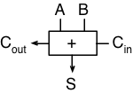
Now rename C to Cin, and Carry to Cout, and we have a “full adder” block that can add two binary digits, including an incoming carry, and generate a sum and an outgoing carry.
And if we put a bunch of them in a row, we can add any N-bit numbers together!
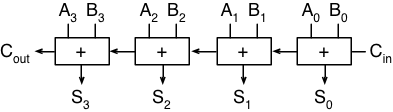
Starting along the top, there are four inputs each of A and B, which allows us to add two 4-bit numbers. The right-most bit, A0, is the “ones”, A1 is the “twos”, and so on through the “fours” and “eights” (powers of two instead of ten). On the far right, we have a dangling carry-in which we’ll just set to zero so that it doesn’t matter.
The carry-out from the right-most adder is passed along to the second adder, just like in long addition: any carry from the “ones” is added to the “twos” column. Finally, on the far left, we get an “extra” carry out, because the addition of two 4-bit numbers may require 5 bits. Normally this is considered an “overflow”, but the carry-out bit is stored in some kind of status register by every CPU that I know of. It just usually can’t be accessed from C or any other language directly, so it gets lost.
Adding in slow-motion
But here’s where the problems come in. Imagine setting up 64 of those adders in a chain, so you could add two 64-bit numbers together. How long would it take? The circuit diagram above shows that each sum goes through one or two gates, and each carry-out goes through two. And the carry-out of one adder becomes the carry-in for the next one. So to generate the entire sum and the final carry-out bit, we need to go through 64 ⋅ 2 = 128 gates.
Uh oh.
Spoiler alert: No CPU has time to wait for 128 gates to flip in sequence, so no CPU actually adds this way. The problem is that the carry bit needs to “ripple” across each bit, and will only scale linearly with the number of bits being added. We’ll need some way to break out of linearity.
Carry-select adder
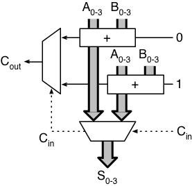
The trick that seems most obvious to me – and the only one I thought of before doing research – was apparently invented in 1960 by Sklansky. If you’re willing to add more circuitry in exchange for speed, you can put two adders in parallel. One computes the sum with a carry-in of 0, and the other computes with a carry-in of 1. When the real carry-in signal arrives, it selects which addition to use. Here’s an example of a 4-bit carry-select adder:
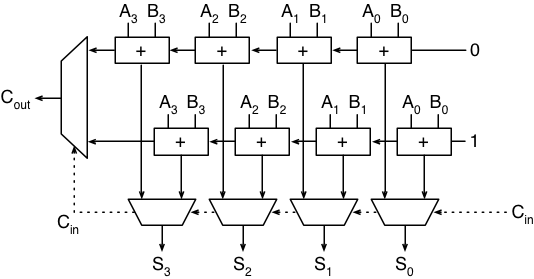
The weird rhombus-shapes are multiplexers, or “mux” for short. A mux takes two inputs and selects one or the other, based on a control signal. In this case, each mux uses the carry-in signal to determine which adder output to use, for each of the four sum bits (along the bottom), and the carry-out bit (on the left).
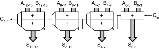
The diagram gets simpler if we make a shortcut box for a series of connected adder units, and draw each group of 4 input or output bits as a thick gray bus:
Now, for example, to compute the sum of two 16-bit numbers, we can split each number into four chunks of four bits each, and let each of these 4-bit chunks add in parallel. When the adders are finished, the carry-out bit from the lowest (rightmost) adder is used to select which adder’s result to use for the next four bits, and then that selected carry-out is used to select the next adder’s result, and so on. Simplifying the diagram a bit more, it looks like:
If we assume a mux takes as long as a logic gate, then this circuit can compute a 16-bit addition in 2 ⋅ 4 + 4 = 12 gate delays: 8 for all the adders to finish, and 4 for the muxs to ripple the carry bits across. For a 64-bit adder, it would take 24 delays, because it would have 16 muxes instead of 4. Going from 128 to 24 is a great start, and it only cost us a little less than twice as many gates!
We can fuss with this and make it a little faster. The leftmost adder unit waits a long time to get its incoming carry bit, and the first 75% of the time is spent waiting for the first adder to finish. If we compute only one bit at a time on the right, then two, then three, and so on as it goes left, we can shave off a few more.
But… we can do better.
Next time, some tricker adding methods that end up being quicker.